Rain Sensors: Gauge In progress
Introduction
The purpose of the project is to measure and record rainfall.
The project requirements are:
- To measure the rainfall over a series of predefined periods
- To display the current rainfall
- To record each period's rainfall in a file on removable storage in a format suitable for importing into a spreadsheet
This page is structured as if there was an orderly, linear process from design to construction. The truth is that process was iterative, through design, construction, testing, redesign and so on. Every single 3D printed component was re-designed and re-printed at least once. I've not gone into all the gruesome details here, because that would make this page much too long and difficult to read. However, some design changes are referred to in the text where the learning point is important.
Design
Design Overview
This project comprises a 3D printed rain gauge coupled to a microcontroller, storage and display.
The gauge collects rain and funnels it down into a pivoted bucket component, comprising two buckets with an attached magnet as shown in figure 1:

The two buckets are pivoted about their common centre point. The mechanism starts off angled so that one bucket is higher than the other. Rain coming in from above fills the raised bucket. When sufficient rain has gathered in the bucket it pivots and empties its contents, bringing the other bucket up under the water flow. The process then repeats.
Each time the buckets pivot the magnet moves past a reed switch causing a pulse to be emitted that can be be processed by a microcontroller.
Rain Gauge Assembly
The rain gauge assembly is designed to capture and funnel rain water onto the buckets shown in figure 1. Renderings of the CAD designs of the components of the assembly are shown in figure 2:

The following list describes the numbered items in figure 2:
- Funnel †
- Case that contains and protects the buckets. The funnel is mounted on top of the case. †
- "Plug" that fits inside the hole at the botton of the funnel that reduces the aperature through which water can flow. ‡
- Buckets & magnet holder †
- Cap to cover the exposed side of the magnet in the magnet holder. ‡
- Bucket pivot unit & reed switch holder †
- Bracket that holds the pivot unit inside the main case ‡
- Mounting brackets to be used to fasten the rain gauge bucket assembly to a wooden baseboard †
Notes:
† Original design by Christopher Barnett, modified by cahamo. Some are adaptations of Christopher's original STL files while others were recreated from scratch.
‡ Original design by cahamo
STL files
The CAD designs were saved as STL files. These files can be downloaded from the cahamo/rain-sensors repository on GitHub.
All files are made available under the Creative Commons - Attribution - Share Alike license v4.0. Files originally created by Christopher Barnett are copyright © 2024 Christopher Barnett. Files created by cahamo are copyright © 2024, Peter Johnson.
Microcontroller
The pulses emitted from the gauge are counted by a microcontroller which calculates the amount rain that must have fallen to trigger each pulse. The total rainfall is displayed on a screen and recorded in memory. Periodically the data is stored on an SD card.
The microcontroller program must be calibrated before use. The amount of rain captured by the funnel and the volume of water needed to tip the pivoted buckets is required to do this. The catchment area of the funnel can be measured. The amount of water that is required for a bucket to tip and empty must be arrived at by experiment.
Construction
Rain Gauge
The rain gauge components described above were 3D printed on a Bambu Labs A1 3D printer using Bambu Basic black PLA. The models were sliced using the Bambu slicer using the default 0.20mm strong print profile and 0.4mm ⌀ nozzle. The following montage shows all the printed parts. The parts are not to scale relative to each other:

A 10mm ⌀ × 3mm deep neodymium magnet was glued into the magnet holder attached to the buckets. The magnet cap was then glued over the exposed part of the magnet. Superglue was used in both cases.

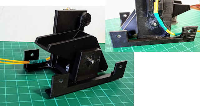
A normally open, plastic bodied reed switch, 2.7mm square section × 14mm long, was soldered to two 20cm lengths of 7/0.2mm stranded wire. The reed switch was then mounted into the provided channel in the bucket pivot unit, securred by superglue. Heat shrink was added to protect sections of the wire. The pivot unit was bolted to its base with 2 × M3 nuts and 10mm hex head bolts.

A 5cm long piece of round 3mm ⌀ mild steel bar was cut to use as an axle that allows the buckets to move within the pivot unit. The axle holes in the pivot unit had to be drilled out to 3.2mm in order for the axle to fit. A M3 washer was threaded over the axle on either side of the buckets to limit side to side movement. The "pimples" surrounding the holes on the side of the buckets component were filed down until the bucket rotated freely on the axle with minimal side to side movement. The axle is a snug friction fit in the pivot unit meaning that the axle remains stationary while the bucket pivots on it. At this stage the wires from the reed switch were glued in place with superglue to avoid them fouling the axle.
Once the interaction of the magnet and reed switch was proved to be working as expected the reed switch was covered in hot melt glue to protect it from the elements.

The funnel plug, that gradually narrows the drain hole, was fitted into the hole at the bottom of the funnel. The plug had to be filed to fit snugly, so that its top was flush with the top of the hole in the funnel. The plug's bottom sits proud of the funnel base and fits through the hole at top of the case. Superglue was run around the joint between the funnel and plug then further filing ensured that the boundary of the funnel plug with the funnel hole was as smooth as possible. The funnel was now bolted to the top of the case using 4 × M5 nuts and 12mm hex head bolts.
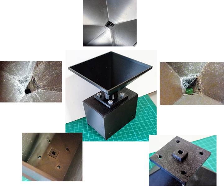
The small images in figure 8, clockwise from top centre are: the holes in the funnel aligned over the case top, as printed; the plug after filing to fit in the bottom of the funnel; the plug protruding from the funnel base; the plug protruding into the top of the case & the plug after gluing in place and filing flush with the funnel hole.
It was now time to assemble the whole gauge. The funnel / casing assembly, gauge assembly and mounting brackets all had their mounting bolt holes drilled out to 3.2mm ⌀ and were then bolted together using 4 × M3 nuts, washers and 16mm hex head bolts. The wires from the reed switch were led out to one side.

Control unit
To follow
Bill of materials
The following components are required:
- 3D printed parts specified in figure 2
- Neodymium magnet: 10mm ⌀ × 3mm deep
- 5cm of 3mm ⌀ circular mild steel rod
- Reed switch: normally open, plastic body, 2.7 square section × 14mm long
- Nuts:
- 6 × M3
- 4 × M5
- Bolts:
- 2 × M3 10mm hex head (any other head type is suitable)
- 4 × M3 16mm hex head (any other head type is suitable)
- 4 × M5 12mm hex head (any other head type is suitable)
- Washers:
- 6 × M3
- Cyanoacrylate glue (superglue)
- Holt melt glue
Calibration
The gauge needs to be calibrated before being used. We need to know how much water is required to tilt a bucket. To do this we pour a measured amount of water through the gauge and count the number of times the bucket tilts. The amount of water required to tilt the bucket is the volume of water put through the gauge divided by the number of tilts counted. It is advisable to run the test several times and to use the average of all the results.
Circuit
An Arduino Nano clone was used to count the number of times the gauge's reed switch closes while pouring water. The count was displayed on a 2×40 character I²C LCD display. To enable several tests to be undertaken sequentially a momentary push button was used to clear the counter. Figure 10 below shows the circuit:

One of the wires from the rain gauge reed switch is coupled to Nano pin D6 while he other connection to the reed switch is connected to ground. Similarly, one terminal of the push switch is connected to Nano pin D2 and the other terminal is also connected to ground. Both pins D2 and D6 are configured as input pins that are pulled up to 5V internally. The I²C display is connected to 5V, ground and to Nano pins A4 and A5, which double as the Nano's SDA and SCL I²C control pins respectively. The Nano is powered by connecting 5V to its 5V pin and ground to a GND pin.
The circuit was built on a breadboard as shown in figure 11 below. The leads from the rain gauge were connected to the circuit via crocodile clips. 5V power was supplied by a breadboard power supply, connected to a 9V wall wart via a barrel jack.

Software
The microcontroller program was written in C++ using VSCode and the PlatformIO extension. The code was targetted at the Arduino platform. The source code is available from the code/gauge-calibration directory of the cahamo/rain-sensors project on GitHub.
Results
10 successful calibration tests performed. For each test a kitchen measuring jug was filled with approximately 800ml = 0.8l of water. This water was poured into the gauge as slowly as possible. After the jug was emptied the number of bucket tilts was read from the LCD and recorded. The count was then reset using the push switch and the experiment was repeated.
The numbers of tilts recorded for each test run were:
| Test # | Number of tilts per 0.8l water |
|---|---|
| 1 | 140 |
| 2 | 131 |
| 3 | 137 |
| 4 | 130 |
| 5 | 139 |
| 6 | 140 |
| 7 | 135 |
| 8 | 137 |
| 9 | 142 |
| 10 | 137 |
The average number of tilts per 0.8 litres of water was 136.8, with a standard deviation of ≈ 3.9.
Calculations
Say we have a funnel with capture area of A mm². The volume of water, Vn, captured by the funnel for n mm of rain is:
Vn = 10-6 × n × A litres
Note that 1 litre = 1,000,000 mm³ = 106 mm³.
So, for one millimetre of rain, the volume of water captured, V1, is:
V1 = 10-6 × A litres
If our rain gauge has a bucket that requires vt litres of water to make it tilt, then the amount of rainfall that causes the bucket to tilt, rt, is:
rt = vt ÷ V1 millimeters
Now my gauge has a funnel with a 100 mm square capture area, so
A = 100 mm × 100 mm = 10,000 mm² = 104 mm².
and
V1 = 10-6 l/mm² × 104 mm² = 10-2 litres = 0.01 litres.
We know that the bucket tilts an average of 136.8 times per 0.8 litres of water, so vt is:
vt = 0.8 ÷ 136.8.
Finally, we can calculate rt:
rt = vt ÷ V1 = (0.8 ÷ 136.8) ÷ 0.01 = 0.5848 mm
to 4 decimal places.
So now we know that every tilt of the bucket represents 0.5848 mm of rainfall. This value will be plugged into the microcontroller program that responds to bucket tilt signal from the rain gauge.
That is as far as things had progressed as at 2025-08-27.